This is the latest in the continuing saga of the next diesel project. The engine is a Kubota Z482 twin cylinder 13.5hp engine from a lorry refrigeration unit. the last instalment saw the crank getting rebuilt as the big ends had gone.
This weeks task was to get the gearbox mounted onto the engine and then the whole power unit mounted into the frame. I want this to be a 'no cuts to the frame' project so it can be a legitimate engine change when it comes to paperwork etc.

After faffing about for hours I cant work out if the engine will just fit or just not fit into the unmodified frame so theres nothing for it other than carry on regardless. Firstly the height of the clutch assembly is taken and 1.0 mm added for clearance.

then support spacers cut to length.

And placed in position ready to weld.

But first I take my dial gauge and check the flywheel. the flywheel is OK but the gap in the main bearings is measurable on the dial gauge. After a brief check of the manual it is within tolerance but will have to be taken into a count a bit later on.
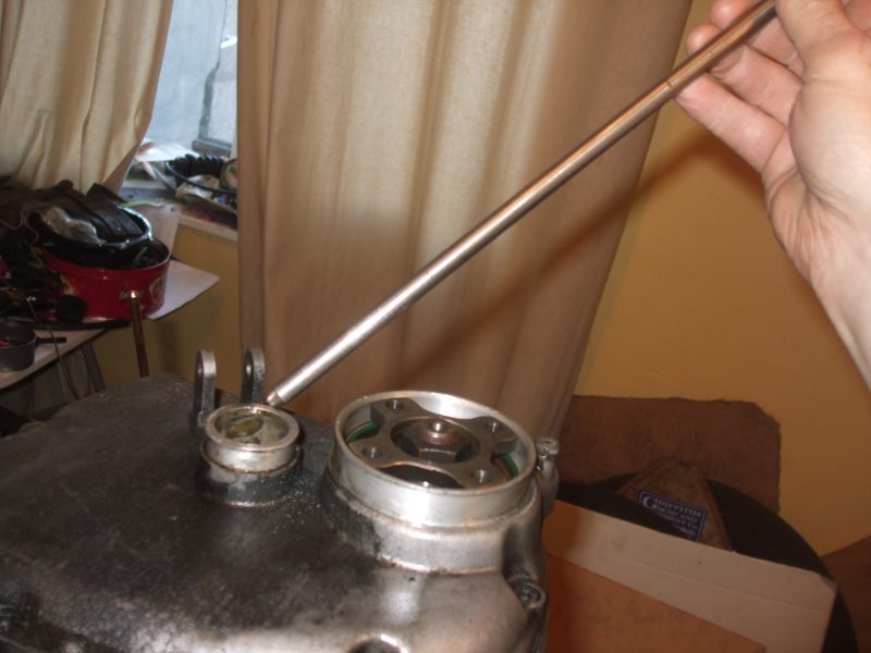
The BMW airhead gearbox has an 8mm push-rod through its middle but the Germans being the nice efficient people we love them for made the hole an accurate 9mm. the upshot is a 9mm piece of ground bar is purchased for cheap and a point is cut on it. The upshot is this will locate in the hole in the gearbox and the accuracy of the ground-bar / hole is so tight it can be ignored.

Pressure is kept on the bar end at all times to ensure it is correctly located on the engine shaft.

Perfection. One end of the spacer bars has already been welded to the gearbox adaptor plate. This will allow me to slide the thing about until its aligned.

The dial gauge is clamped onto the engine and pointed on the gearbox. Pushing from side to side there is a constant 0.15mm free moment when the gearbox is jiggled from side to side.

After much jiggling and tapping I'm convinced it is located in the middle of the free play and the whole thing is welded solid.

However after welding its not centralised. When I push the rod up to the engine shaft it is consistently pushed to one side, there is nothing for it but alter the centres of something.

The direction for correction is marked.

Then one side is filed away and the other bashed with a hammer (Oh for a proper blacksmiths anvil) so the metal is expanded and the hole is closed and so on....

Eventually I'm convinced I cant get it any better as I reach the limit of my measuring devices.

Then the whole assembly is put in the frame and jiggled about and chocked up on bits of wood and scrap until it goes in the frame.

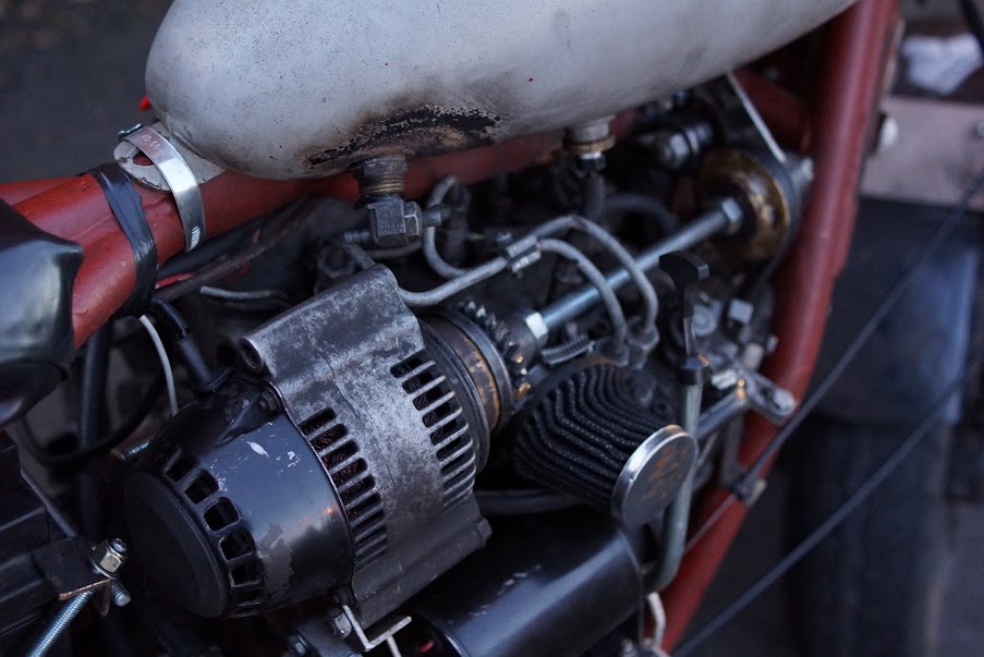
It rather looks like it should be there

Free space on the out put of the gearbox.

The rocker cover can be removed so the valve clearance can be adjusted and the 710 cap accessed.

This side of the engine clears the frame.

So does this side.

Perfection!!!

The next problem is how to hold it all steady whilst I make the engine mounting brackets.

After a really hot cup of tea I decide to simply weld it in place and then cut the welds away after the brackets have been made.

Thus

And thus, three points should do it.

Left template.

Right template.

A conveniently sized bit of steel from the scrap skip last time I visited the steel supplier.

Because a double bend is needed and I cant find my larger hammer and don't have a blacksmiths anvil I decide to cut the bracket in half so I only have to do one bend then simply weld the two bits together.

Weldy, weldy, stick weld.

Knock the flux away

Same goes for the other side.

Weldy, weldy, my house is on fire!!!!

Another perfect weld
So that's it, the engine is mounted in the frame and no frame cutting or adaptation of the engine was required.
The list of things to do is almost infinite, so I'll have another beer and forget about it for the night.
.